
Automated Ethernet-APL Power & Data Conformance Testing
(Budget for Load/Sensor)

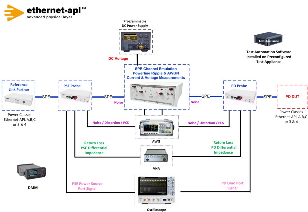
Telebyte’s Ethernet-APL Universal Test Setup supports PD Load ports with one setup for Ethernet-APL Conformance and Interoperability Data and Power testing. The small footprint saves valuable laboratory test space while the fully automated approach saves time and money and provides repeatable test results. The solution is easy to use, allowing tests to be performed by technicians with minimal training. There is no need to plug/unplug different instruments and fixtures in the test setup. Additional features include automated software for controlling DUTs and all test equipment. The software generates Pass / Fail Reports for Ethernet-APL Conformance Power and Data tests. A customer’s PC with a serial and network connection is used to transfer data to the PC for post processing the captured Ethernet signal with Telebyte’s Test Automation Software. Customers may purchase all integrated test setup instruments from Telebyte. Please note this same setup (with the addition of a DC programmable load) can be used for testing PSE switches. An optional switch matrix is available for switching in of multiple DUTs in a test bed.
Required equipment:
Ethernet Conformance Data and Power Test List
Ethernet-APL Data Test Specification v1.5.6 | |||
Group 1: Transmitter Electrical Measurements | |||
Test APL.146.1.1 – Transmitter Output Voltage (Test Mode 1) | |||
Test APL.146.1.2 – Transmitter Output Droop (Test Mode 2) | |||
Test APL.146.1.3 – Transmitter Timing Jitter (Test Mode 1) | |||
Test APL.146.1.4 – Transmitter Power Spectral Density (PSD) and Power Level (Test Mode 3) | |||
Test APL.146.1.5 – Transmit Clock Frequency (Test Mode 1) | |||
Test APL.146.1.6 – MDI Return Loss (Part A: Tx disabled: DUT in Slave, high Z state) | |||
Test APL.146.1.6 – MDI Return Loss (Part B: Test Mode 3 VNA with narrowband IF of 100Hz) | |||
Test APL.146.1.7 – Transmitter Distortion (Test Mode 2) with 1MHz Sinusoidal Disturber at 1.0Vpp and/or 2.4Vpp | |||
Group 2: Receiver Electrical Measurements | |||
Test APL.146.2.1 – Receiver Packet Error Rate Stress Test | |||
Noise includes | |||
AWGN @ -106dBm/Hz | |||
Power-line Ripple Noise components | |||
100mV at 1kHz and 10kHz, 10mV at 100kHz and 1MHz, and | |||
100mV at 10kHz falling 20dB per decade to 10mV at 100kHz swept | |||
Ethernet-APL Appendix F – 1.0Vpp Spur & 2.4Vpp Trunk Worst-Case Whole Communication Channel | |||
Traffic Testing – Link Quality SNR better than 20dB, DUT Passing BER < 10-9 | |||
Group 3: Transmit Packet Formation | |||
Test APL.146.3.1 – Transmit Signaling | |||
Group 4: Receive Error Handling | |||
Test APL.146.4.1 – Automatic Polarity Detection and Correction | |||
Test APL.146.4.2 – Handling of Received ESD_ERR4 | |||
Test APL.146.4.3 – Handling of Received CRC Errors | |||
Section 98: Ethernet-APL Clause 98 Auto-Negotiation Validation | |||
Group 1: Auto –Negotiation Basic Tests for Ethernet-APL | |||
Test APL.98.1.1 – Advertisement and Auto-Negotiation Verification | |||
Part A: DUT advertises valid capabilities | |||
Part B: DUT links with compatible link partner | |||
Part C: DUT spur port when LP advertises but does not request increased transmit level | |||
Part D: DUT behavior with incompatible link partner (spur to trunk, trunk to spur) | |||
Part E: DUT behaves properly with incompatible link partner (spur to trunk, trunk to spur) | |||
Part F: DUT behavior when link partner prefers master or slave port role (M/S is always 0). | |||
Part G: DUT behavior when link partner forces master or slave port role (M/S is always 1). | |||
Test APL.98.1.2 – Management Restart of Auto-Negotiation | |||
Test APL.98.1.3 – Link Status Fail | |||
Test APL.98.1.4 – DME Voltage Envelope Test | |||
Test APL.98.1.5 – Auto-Negotiated Link-Up Time | |||
Ethernet-APL Power Test Specification v1.4 | |||
TL.1 Power Tests | |||
TL.1.1 Minimum Current Draw Minimum Supply Voltage 28.8 V | |||
TL.1.1 Minimum Current Draw Maximum Supply Voltage 50V | |||
TL.1.2 Inrush Current | |||
TL.2 Electrical Characteristics | |||
TL.2.1 Differential In-Band Ripple and Noise | |||
TL.2.2 Differential Out-Band Ripple and Noise | |||
TL.2.3 Current Derivatives | |||
TL.2.4 Current Events Maximum Supply Voltage 50V | |||
TL.2.5 Under Voltage Current | |||
TL.3 General Port Requirements | |||
TL.3.1 Terminal and Connectors | |||
TL.3.2 Shielding Options* | |||
TL.3.3 Polarity Sensitivity Mode A + / – | |||
TL.3.3 Polarity Sensitivity Mode B – / + | |||
SL: Spur Power Load Ports – Segment ‘S’; Port ‘L’ | |||
SL.1 Power Tests | |||
SL.1.1 Minimum Current Draw Minimum Supply Voltage UPL(min) Class A=9V ClassC =10.6V | |||
SL.1.1 Minimum Current Draw Maximum Supply Voltage UPL(min) Class A and C = 15V | |||
SL.1.2 Inrush Current | |||
SL.2 Electrical Characteristics | |||
SL.2.1 Differential In-Band Ripple and Noise Maximum Supply Voltage UPS(max) Class A and C = 15V | |||
SL.2.1 Differential In-Band Ripple and Noise Minimum Load Voltage UPL(min) Class A=9V ClassC =10.6V | |||
SL.2.2 Differential Out-Band Ripple and Noise Maximum Supply Voltage UPS(max) Class A and C = 15V | |||
SL.2.2 Differential Out-Band Ripple and Noise Minimum Load Voltage UPL(min) Class A=9V ClassC =10.6V | |||
SL.2.3 Current Derivatives Maximum Supply Voltage UPS(max) Class A and C = 15V | |||
SL.2.3 Current Derivatives Minimum Load Voltage UPL(min) Class A=9V ClassC =10.6V | |||
SL.2.4 Current Events Minimum Load Voltage UPL(min) Class A=9V ClassC =10.6V | |||
SL.2.4 Current Events Maximum Supply Voltage UPS(max) Class A and C = 15V | |||
SL.2.5 Under Voltage Current | |||
SL.3 General Port Requirements | |||
SL.3.1 Terminal and Connectors | |||
SL.3.2 Shielding Options* | |||
SL.3.3 Polarity Sensitivity Mode A + / – | |||
SL.3.3 Polarity Sensitivity Mode B – / + | |||
* External DMM required (KT-34465A direct measurement)